
May-2012
Spent sulphuric acid regeneration (SAR) process
Several chemical processes utilise concentrated sulphuric acid as a catalyst or dehydrating agent, in which the acid becomes “spent”; ie, weakened and/or contaminated
Linda Colby and John Recar, MECS Inc
Viewed : 74956
Article Summary
In a few cases, this spent acid may be safely disposed or used in other processes, but usually it must be regenerated back to relatively pure and concentrated acid for reuse in the main process, over and over. The major processes include alkylation to produce high-octane gasoline, nitration to produce explosives and pesticides, and the acrylonitrile (AN) and methyl methacrylate (MMA) processes. The sulphuric acid regeneration (SAR) plant processes for all of these feeds are essentially the same, with consideration given to the organic and inorganic contaminants, overall water balance, and the desired product specifications. These plants may be readily designed to produce fresh sulphuric acid in concentrations from 93% acid to 40% oleum, with 99.2% H2SO4 typical for alkylation use.
SAR plants are being routinely designed by several engineering firms, most notably MECS, Inc, a DuPont subsidiary. The majority of these SAR plants support petroleum refineries to produce high-octane gasoline. Many of these plants use only the spent sulphuric acid as the feedstock, but some also include hydrogen sulphide, sulphur, or sulphur-containing organic compounds. Where there are several refineries in a region, a single-contract SAR plant may be built to service all of those refineries. Single-train SAR plants have been built in capacities ranging from 35 to 1800 STPD of product acid.
The SAR plant design includes four processing sections: thermal decomposition, gas cleaning, conversion and absorption. Heat recovery from thermal decomposition, exothermic conversion and absorption reactions is typically in the form of high-pressure, superheated steam, which is optimissed based on site needs and economics. Thermal energy may also be recovered as hot water for space heating or as process-to-process heat exchange, where applicable.
The thermal decomposition section consists of fuel burner(s) and spent acid atomisation into a large brick-lined decomposition furnace, where the acid is vapourised and decomposed into SO2, H2O and O2, at a temperature near 1000°C. In order to maximise the yield of SO2, the combustion is controlled at very near stoichiometric quantities of fuel and air. Natural gas, refinery gas or light fuel oils are most often used for the fuel, but heavy oil may be used with some added control and ash removal issues. If the ratio of fuel to oxygen is not very well controlled, elemental sulphur will be produced, which will solidify in the gas cleaning system, leading to plugging and plant shutdown for cleaning.
When feeds or fuels contain nitrogen compounds, or where very low NOx emissions are required, two-stage combustion systems are included. The hot combustion gases are cooled in a high-pressure boiler and, in some cases, a downstream superheater or radiant heat exchanger, which recovers heat for the conversion section of the plant. The radiant heat exchangers are generally used for small plants (less than 100 MTPD), while steaming equipment is used for larger capacity plants.
The gas cleaning section of the plant serves two functions: remove any ash or solid impurities from the gas, and reduce the water vapour content to allow production of the desired acid concentration. Typically, four or five different units are combined in series for this section of the SAR plant. The first unit is an adiabatic scrubber, using weak acid to saturate and reduce the temperature of the gas from about 300°C to about 80°C, along with some solids removal. Open spray towers, Venturi scrubbers or froth contactors are typically used for this primary scrubber, with the MECS DynaWave scrubber preferred as having the best combination of capital cost, energy usage, solids removal and low maintenance.
Gas cooling with condensation of excess water vapour is completed in the second unit, which may be direct or indirect contact using cooling tower water as the heat sink. Indirect heat exchangers using graphite-tubed or lead-tubed heat exchangers were often used in the past, but have lost favour due to high cost and high maintenance. Most plants today utilise direct contact, packed gas cooling towers for this service. The circulating weak acid is cooled in high-alloy plate-type heat exchangers.
The third unit, usually called the polishing or final scrubber, is needed to further capture dust/ash particles, which have been agglomerated in upstream gas cleaning equipment and/or gaseous contaminants such as chlorides or fluorides. This is typically a second MECS DynaWave scrubber, without additional cooling.
The final gas cleaning unit is necessary to capture essentially all of the remaining dust/ash particles and the acid mist formed from the hydration of the small amount of undecomposed SO3 present. If the dust and ash particles are soluble in weak sulphuric acid (ie, iron salts), fibre bed mist eliminators, such as MECS Brink series, are preferred for their low capital and low maintenance characteristics. Solubility in weak sulphuric acid is typical for most spent acid from refinery and nitration processes. If the dust and ash solids are not soluble in weak acid, electrostatic mist precipitators are required.
The SO2 bearing gas is then dried by contact with 93 to 96% H2SO4 in a packed bed acid tower or drying tower. This unit is similar in design and operation to others in the SO3 absorption system, and will be discussed there.
The acid plant main gas blower drafts the process gases from the inlet of the decomposition furnace through the gas cleaning units, and forces them through the remaining sections of the plant. This is typically a single-stage centrifugal compressor, either motor or turbine driven, operating from an inlet of approximately 0.1 bar to discharge at 0.4 to 0.7 bar. Parallel compressors are sometimes selected for very large plants or to provide added on-stream reliability.
Conversion of SO2 to SO3 is done in a multistage fixed-bed converter vessel, containing several stages of vanadium pentoxide catalyst. (MECS involvement in the design of sulphuric acid plants began almost 100 years ago with the early development of vanadium pentoxide catalysts. Today, through continuous research and development and the world’s largest dedicated sulphuric acid catalyst plant, MECS remains the leader in providing a variety of sulphuric acid catalysts, specially blended to provide the optimum activity, hardness and resistance to thermal degradation.) The reaction is initiated by preheating the SO2 and O2 containing process gas to a little over 400°C before the first catalyst stage.
Add your rating:
Current Rating: 3


-
 MINIFLASH - the safety standard in flashpoint testing
-
 GEA Liquid Jet Mixer
-
 Renewable fuels technology from Honeywell UOP
-
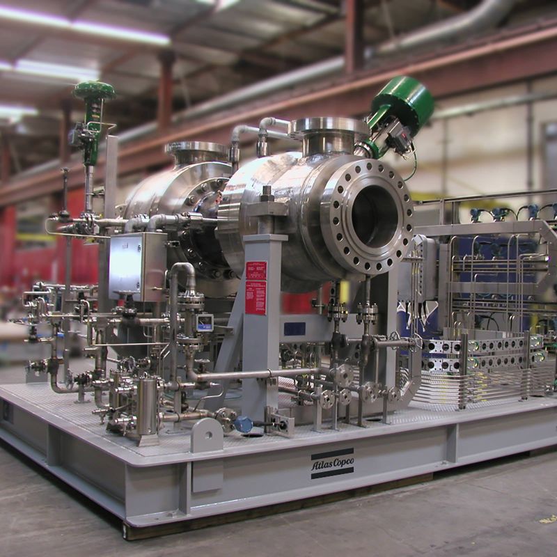 Atlas Copco Energas expander compressors
-
 Cognite Atlas AI™
-
 BASF FCC Refining Catalysts
-
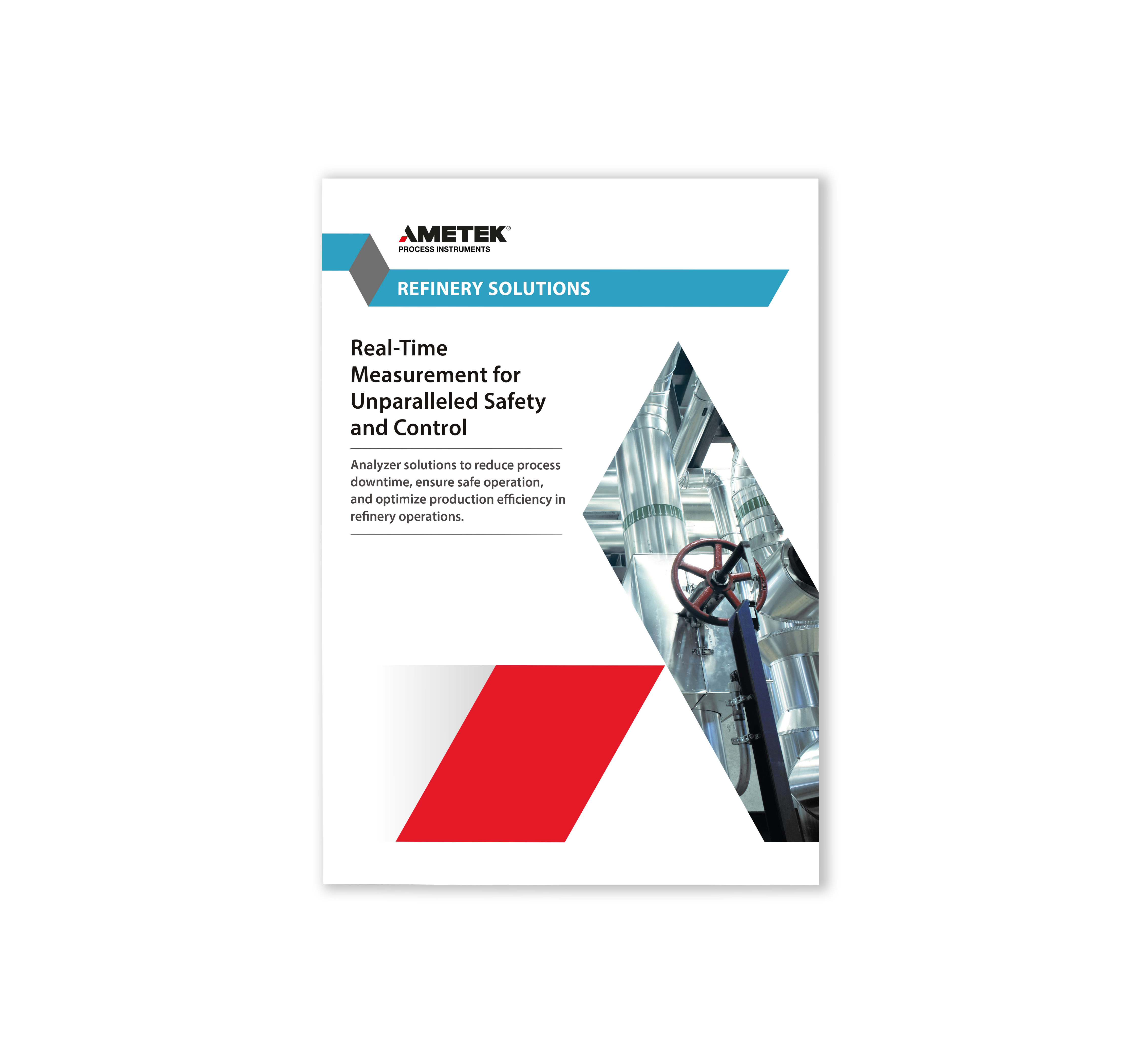 AMETEK Process Instruments Refinery Solutions
-
 FCC catalyst solutions
-
 Level and density in FCC processes from Berthold
-
 Axens SAF Solutions
SPONSORS