Sep-2014
How to select best meg recovery unit’s configuration?
The formation of hydrates in deep sea natural gas tie-back lines had been traditionally inhibited by injecting Triethylene Glycol (TEG) or Methanol at the subsea manifold.
Jérémie Esquier
Prosernat
Viewed : 10777
Article Summary
Unfortunately, gelling of the TEG at the manifold or in the delivery umbilical and lack of recovery of the methanol were persistent drawbacks to their continuous use. CCR Technologies Ltd. (CCR) was instrumental in moving the offshore flow assurance mindset away from TEG and Methanol and towards Monoethylene Glycol (MEG) as the hydrate inhibitor of choice for multiphase tie back production lines. CCR designed and delivered the first commercial MEG Recovery Unit (MRU), which was started up in 1999 for Shell Mensa WD-143 Offshore Project in the Gulf of Mexico, USA. At the time, Mensa was the deepest off-shore production in the world with the MRU on-line >95% since then.
Flow Assurance can be loosely defined as ensuring that production is delivered from the wells to the downstream processing facility with a high level of availability. The injection of Lean Glycol (to avoid hydrate formation) is part of that Flow Assurance Loop. Therefore, it is critical to understand the production profile and glycol needs throughout the life of the facility so that the MRU can be properly designed. The MRU may include Pre-Treatment, Regeneration, and Reclamation in several different configurations.
This paper outlines some of the information required to properly specify a MRU and follows the decision points and opportunities for optimisation that arise as the design develops from initial concept to a more detailed proposal. Although the MRU is typically considered a utility within the plant, the impact it can have on flow assurance should not be overlooked.
Following an agreement signed between CCR and Prosernat, Prosernat is now the exclusive licensor of the MEG Reclaiming patented and proprietary process developed by CCR.
Introduction
A newly discovered field located 50 km off-shore, will be developed over the next five years with production expected to come on-line in 2019. The production will be brought onshore where it will be processed and delivered to customers and other downstream processes. Given the location of the subsea wells and the production pressure/temperature profile, glycol injection will be used to prevent the formation of hydrates. The Process Design Basis (Table 1) shows the information received from the Flow Assurance Engineer.
Rich MEG delivered to the MEG Recovery Unit typically comes from the plant slug catcher and inlet separator. This liquid feed typically contains a high level of dissolved hydrocarbons (range 0.5-2.0 vol%), including a high concentration of CO2. If left in solution, these hydrocarbons could accumulate in the process, leading to foaming, reduced boiling, or throughput issues with the Vacuum Compressor. In order to remove these dissolved hydrocarbons, a Rich MEG Flash Vessel will be included in the design.
MEG Recovery Unit Configuration
The Rich MEG has a salt content of 2.4 wt% and the Lean MEG specification is 85 wt% MEG on a salt-free basis. Assuming the Regenerator section of the MRU only removes water, the Lean MEG exiting the Regenerator will contain 5.82 wt% salts. At this level of salts, the Lean MEG will contain free solids which will precipitate out inside the Regenerator. This precipitation will likely occur on the outside of the tubes in the kettle reboiler, which will lead to scaling, fouling, local hot spots, and reduced throughput.
There are several different configurations and options that can be considered as part of the MEG Recovery Unit. Figure 1 provides a high level decision tree that can be used to determine which configuration and options are appropriate for any application. There is some leeway in the application of this tool which is based on experience gained during the last 15 years.
It has already been determined that a conventional Regenerator will result in precipitated salts, which leads us to an Integrated Regenerator and Reclaimer design. The Integrated unit achieves the water removal (Regeneration) and salt removal (Reclamation) in a single process. It was also identified above that there would be the need for some level of Pre-Treatment due to the high level of dissolved hydrocarbons. A Process Flow Diagram of the chosen configuration is shown in Figure 2.
If the selection process above came up with a Conventional Regenerator and Slipstream Reclaimer, a detailed salt study should be carried out. This salt study investigates the individual salt species (cations and anions) and determines their accumulation, solubility, and likelihood of scaling throughout the entire Flow Assurance Loop. Using the results of this study, the optimum amount of salt removal can be determined which will result in a smaller Reclaimer Process. The study will also determine what level of Divalent Cation Removal (DCR) is necessary.
Process Description
The Rich MEG is fed to the unit from the upstream facilities and letdown across the inlet level control valve. This valve reduces the pressure of the Rich MEG, allowing some of the dissolved hydrocarbons to vaporise out of the solution.
Sufficient residence time is included in the design of the Rich MEG Vessel and three product streams exit the vessel. The hydrocarbon liquids and vapours are directed off-skid to appropriate hydrocarbon handling systems such as a low pressure flare or hydrocarbon drain system. The pH-adjusted Rich MEG is directed into the Reclaimer Flash Drum.
Vapours exiting the Reclaimer Flash Drum are directed into the MEG Still Column. Both of these vessels operate at sub-atmospheric pressure. This allows the MEG/water mixture entering the vessel to vaporise at a temperature well below the degradation temperature of MEG (about 165°C). Upon flashing into the column, water and MEG will vaporise while Salts and other solids contained in the inlet stream will not vaporise and will instead become concentrated in the slurry within the Reclaimer Flash Drum.
MEG/H2O/salt slurry is continuously pumped from the bottom of the Reclaimer Flash Vessel through the Reclaimer Circulation Heater by a horizontal, centrifugal circulation pump.
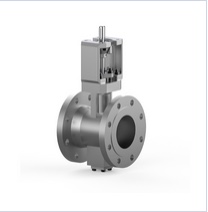
Boiling of the slurry circulating through the Reclaimer Circulation Heater is undesirable as it would result in solids deposition which would very rapidly foul the heat transfer surfaces. Boiling is therefore deliberately suppressed by imposing a “back pressure” on the heater using a specific device. In addition, a large circulation rate is maintained through the heater to minimise the temperature rise of the slurry, the skin temperature inside the exchanger, and the time the slurry is in contact with the heat transfer surfaces. Use of these design techniques nearly eliminates the potential of fouling of the heat transfer surfaces even with divalent cations present.
Upon entering the Reclaimer Flash Vessel, the water and MEG contained in the slurry will vaporise and flow upward through the vessel while the residual droplets of MEG/H2O/salt slurry fall into the liquid pool in the base of the vessel. As a result, the salt and solids concentration of the liquid pool increases.
Add your rating:
Current Rating: 4


